In order to offer you the best possible experience, we suggest that you accept the deposit and reading of cookies and the use of technology necessary for their proper functioning:


Using these steel grades makes it possible to build longer/higher booms for cranes and aerial platforms.
These low alloy steel grades complete the Amstrong® range (see data sheet A20) and offer exceptionally high yield strength values. They have a fine grain structure, low carbon content for improved weldability, and controlled internal purity.
Weight reduction
The grades in this data sheet combine outstanding mechanical properties (very high strength, fatigue resistance and toughness) with good formability and weldability. Their guaranteed high yield strength makes it possible to achieve substantial weight reduction through downgauging, whilst maintaining overall performance and safety. These steel grades are therefore frequently used to replace conventional structural steel grades when weight reduction is required.
Thickness reduction brings additional savings when processing the material, since it is easier to weld, and reduces transport costs. Further savings are also achieved in service, in the form of lower energy consumption, improved mechanical performance, safety etc.
Abrasion/wear resistance
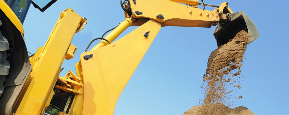
In some applications (conveying devices, earth-moving or transportation vehicles etc), the steel surface can be subject to wear. Wear is a complex physical phenomenon that depends not only on the presence of abrasive materials but also on the conditions under which it occurs (pressure, temperature, impact, corrosion etc).
Compared with standard structural steel grades, Ultra High Strength Steel grades allow a significant improvement in wear resistance. In many cases, they can be more economical and easier to process than steel grades specifically designed for wear resistance.
Their very high yield strength contributes to a solution that increases the payload capacity and gives higher strength structures.
Typical applications include telescopic cranes, aerial platforms, concrete pumps, telescopic handlers, tippers and truck trailers, where the emphasis is on strength and weight reduction potential.
Thermal cutting
These grades are suitable for oxygen, plasma and laser cutting.
Estimation of the possible thickness reduction
When switching from grade 1 (with low yield strength) to grade 2 (proposed in this data sheet), an estimation of the thickness reduction that can be achieved is given by the following formula:
t2 = t1 (Re1/Re2)½
where t = thickness Re = yield strength
Please note that other issues, such as fatigue resistance, need to be checked before reducing thickness.
These grades are available in "A - Unexposed" finish only.
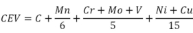
Weldability and cold crack susceptibility of these grades are more accurately assessed using the PCM formula (parameter crack measurement), which was developed for low carbon steels (< 0.11%).
Due to their typical low carbon equivalent value (PCM < 0.25), these ArcelorMittal grades do not need to be pre- or post-heated when welding. They are not prone to excessive hardening due to their low carbon and low alloy content, are totally insensitive to cold cracking and are suitable for all types of arc welding.
| Thickness range | CEV typical | PCM typical | |
|---|---|---|---|
| Amstrong® Ultra 650MC | ≤ 12 mm | 0.42 | 0.18 |
| > 12 mm | 0.45 | ||
| Amstrong® Ultra 700MC | < 6 mm | 0.37 | 0.16 |
| 6 < 10 mm | 0.43 | 0.18 | |
| ≥ 10 mm | 0.45 |
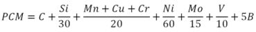
Heat-affected zone softening - welding recommendations
If special care is not taken, softening may occur in the heat-affected zone (HAZ), particularly in the intercritical heat-affected zone (ICHAZ), which is typical behaviour of thermomechanically rolled steel grades with yield strength above 500 MPa. The extent of softening and the width of the softened zone increases with heat input applied during welding.
In order to preserve the high mechanical properties of the base material after welding, the recommendation is to limit the welding energy to about 1.5 kJ/cm per millimetre of thickness, as shown in the figure below, which corresponds to the following maximum cooling times (between 800°C and 500°C):
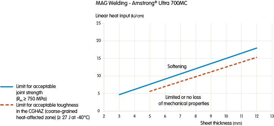
Recommendations for selecting the suitable heat input for MAG welding of Amstrong® Ultra 700MC grade.
Interpass temperature & heat treatment
Amstrong® Ultra 650MC and Amstrong® Ultra 700MC do not need to be pre- or post-heated when welding. In multi-pass welding, the interpass temperature acts as preheating for the subsequent pass and increases cooling time. The interpass temperature should therefore be limited to minimise any loss in mechanical properties. The maximum recommended interpass temperature is 100°C.
Similarly, post-weld heat treatment may cause loss in mechanical properties. We therefore strongly recommend that you contact ArcelorMittal prior to performing any heat treatment, to define the suitable settings.
Filler wire selection
We recommend using filler wires that at least match or overmatch the strength of the base material. Recommended wires/fluxes for Amstrong® Ultra 700MC are listed in the table below.
| Supplier | SMAW | GMAW | FCAW | SAW | |
|---|---|---|---|---|---|
| Esab | OK 75.75 | OK Autrod 13.29, OK Aristorod 13.31 | OK Tubrod 14.03 | OK Autrod 13.43 | OK Flux 10.62 |
| Filarc | Filarc 118 | Filarc PZ 6148 | |||
| Lincoln | Conarc 80 | LNM MoNiVa | Outershield 690-H | LNS 168 | P230 |
| Conarc 85 | Outershield MC-100 | LA 100 | Lincolnweld 8500 | ||
| Oerlikon | Tenacito 80 CL | Carbofil NiMoCr | Fluxofil 42 | OE-S3 NiMoCr | OP 121TT |
| Tenax 118M | Carbofil MnNiMo | Citoflux M07 | Fluxocord 42 | ||
| S.A.F. Air Liquide | Safer ND 80 | Nertalic 88 | Steelcored 42 | ||
| Safdual 270 | |||||
| Thyssen | SHNK 100 | Union NiMoCr | Union S3 NiMoCr | UV 421TT | |
Mechanical properties after welding
When welded within the recommended heat input range, the tensile strength and the impact toughness of the welded area of Amstrong® Ultra 650MC and Amstrong® Ultra 700MC steel grades are superior to the minimum requirements of European standards EN 288 and EN 10149 relating to the base metal.
The fine grain size and low sulphur content improve the fatigue resistance of the steel. Fatigue performance is measured by uniaxial tests at different stress levels. These values are used to plot the Wöhler curve and determine the endurance limit of the steel grade.
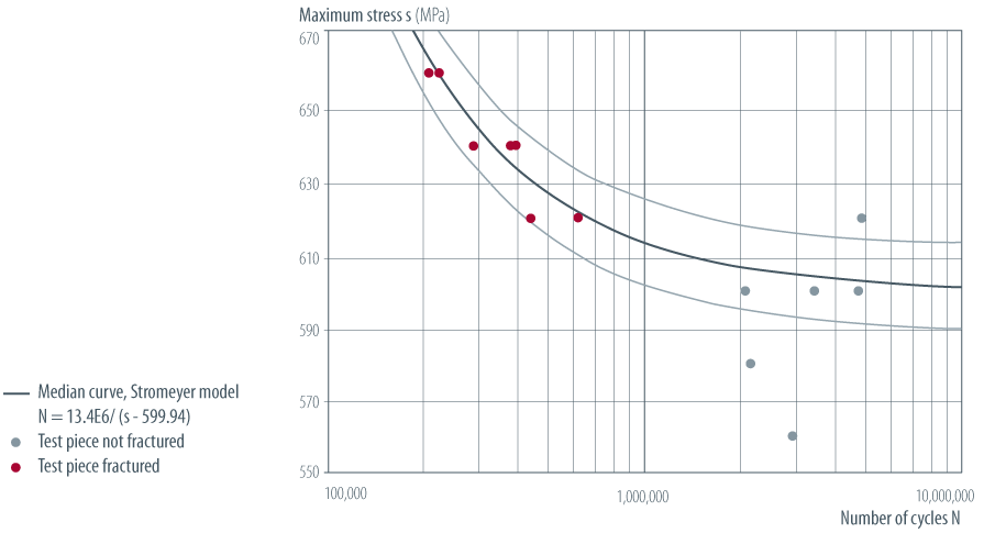
Typical Wöhler curves of Amstrong® Ultra 700MC show an endurance limit above 560 MPa (with R = 0.1).
However, it should be noted that it is advisable - as with most materials - to keep welded joints away from highly stressed zones, particularly in the case of dynamic loading, since they may adversely affect fatigue endurance.
| EN 10149-2:2013 | NF A 36-203:1992 | BS 1449/1 | SEW 92* | USA ASTM | Old brand names | |
|---|---|---|---|---|---|---|
| S650MC EN 10149-2 | S650MC | (QstE 690TM) | ||||
| Amstrong® Ultra 650MC | ||||||
| S700MC EN 10149-2 | S700MC | (E690D) | ||||
| Amstrong® Ultra 700MC | S700MC | (E690D) | 75F70 | A514 |
() Closest grade as no fully equivalent grade exists.
* The values for the tensile test of these steel grades apply to transverse test pieces.
| S650MC EN 10149-2 | |
|---|---|
| EN 10149-2:2013 | S650MC |
| NF A 36-203:1992 | |
| BS 1449/1 | |
| SEW 92* | (QstE 690TM) |
| USA ASTM | |
() Closest grade as no fully equivalent grade exists.
* The values for the tensile test of these steel grades apply to transverse test pieces.
| Amstrong® Ultra 650MC | |
|---|---|
| EN 10149-2:2013 | |
| NF A 36-203:1992 | |
| BS 1449/1 | |
| SEW 92* | |
| USA ASTM | |
* The values for the tensile test of these steel grades apply to transverse test pieces.
| S700MC EN 10149-2 | |
|---|---|
| EN 10149-2:2013 | S700MC |
| NF A 36-203:1992 | (E690D) |
| BS 1449/1 | |
| SEW 92* | |
| USA ASTM | |
() Closest grade as no fully equivalent grade exists.
* The values for the tensile test of these steel grades apply to transverse test pieces.
| Amstrong® Ultra 700MC | |
|---|---|
| EN 10149-2:2013 | S700MC |
| NF A 36-203:1992 | (E690D) |
| BS 1449/1 | 75F70 |
| SEW 92* | |
| USA ASTM | A514 |
() Closest grade as no fully equivalent grade exists.
* The values for the tensile test of these steel grades apply to transverse test pieces.
() Closest grade as no fully equivalent grade exists.
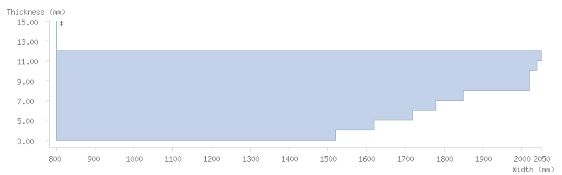
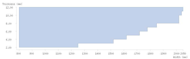
| Thickness (mm) | Min width | S650MC EN 10149-2, Amstrong® Ultra 650MC | S700MC EN 10149-2, Amstrong® Ultra 700MC |
|---|---|---|---|
| Max width | Max width | ||
| 2.00 ≤ th < 3.00 | 800 | - | 1250 |
| 3.00 ≤ th < 4.00 | 1520 | 1520 | |
| 4.00 ≤ th < 5.00 | 1620 | 1620 | |
| 5.00 ≤ th < 6.00 | 1720 | 1720 | |
| 6.00 ≤ th < 7.00 | 1780 | 1780 | |
| 7.00 ≤ th < 8.00 | 1850 | 1850 | |
| 8.00 ≤ th < 10.00 | 2020 | 2020 | |
| 10.00 ≤ th < 11.00 | 2040 | 2040 | |
| 11.00 ≤ th < 12.00 | 2050 | 2050 | |
| 12.00 ≤ th < 15.00 | * | - |
* Please contact us.
Pickled
Available on request. Please contact us.

| Thickness (mm) | Min width | Max width |
|---|---|---|
| 2.00 ≤ th < 3.00 | 800 | - |
| 3.00 ≤ th < 4.00 | 1520 | |
| 4.00 ≤ th < 5.00 | 1620 | |
| 5.00 ≤ th < 6.00 | 1720 | |
| 6.00 ≤ th < 7.00 | 1780 | |
| 7.00 ≤ th < 8.00 | 1850 | |
| 8.00 ≤ th < 10.00 | 2020 | |
| 10.00 ≤ th < 11.00 | 2040 | |
| 11.00 ≤ th < 12.00 | 2050 | |
| 12.00 ≤ th < 15.00 | * |

| Thickness (mm) | Min width | Max width |
|---|---|---|
| 2.00 ≤ th < 3.00 | 800 | 1250 |
| 3.00 ≤ th < 4.00 | 1520 | |
| 4.00 ≤ th < 5.00 | 1620 | |
| 5.00 ≤ th < 6.00 | 1720 | |
| 6.00 ≤ th < 7.00 | 1780 | |
| 7.00 ≤ th < 8.00 | 1850 | |
| 8.00 ≤ th < 10.00 | 2020 | |
| 10.00 ≤ th < 11.00 | 2040 | |
| 11.00 ≤ th < 12.00 | 2050 | |
| 12.00 ≤ th < 15.00 | - |
* Please contact us.
Pickled
Available on request. Please contact us.
Toughness
The fine grain size and low sulphur and carbon content of these Amstrong® Ultra grades improve steel toughness.
For this reason, the option proposed by EN 10149:2013 for this characteristic is included in our Amstrong® Ultra range.
Two versions of Amstrong® Ultra 650MC and Amstrong® Ultra 700MC are available:
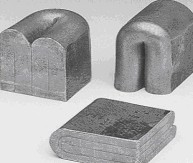
Bending
The minimum 180° bending radius of Amstrong® Ultra 650MC and Amstrong® Ultra 700MC can vary according to the edge quality of the sheet:
| Notes | Direction | Thickness (mm) | Re (MPa) | Rm (MPa) | A80 (%) | Min. mandrel diameter for 180° bending | KV -20°C (J) | KV -40°C (J) | A 5.65√So (%) | |
|---|---|---|---|---|---|---|---|---|---|---|
| S650MC EN 10149-2 | 1 | L | 2 - 3 | ≥ 650 | 700 - 880 | ≥ 10 | - | - | - | - |
| 3 - 8 | - | ≥ 12 | ||||||||
| 8 - 10 | ≥ 630 | |||||||||
| T | 2 - 10 | - | - | - | ≥ 2 x t | - | - | - | ||
| Amstrong® Ultra 650MC | 2+1 | L | 2 - 3 | ≥ 650 | 700 - 850 | ≥ 10 | - | - | - | - |
| 3 - 6 | - | ≥ 14 | ||||||||
| 6 - 8 | ≥ 40 | ≥ 27 | ||||||||
| 8 - 12 | ≥ 630 | |||||||||
| T | 2 - 3 | ≥ 670 | 710 - 880 | ≥ 10 | ≥ 1.8 x t | - | - | - | ||
| 3 - 8 | - | ≥ 12 | ||||||||
| 8 - 15 | ≥ 650 | |||||||||
| S700MC EN 10149-2 | 1 | L | 2 - 3 | ≥ 700 | 750 - 950 | ≥ 10 | - | - | - | - |
| 3 - 8 | - | ≥ 12 | ||||||||
| 8 - 10 | ≥ 680 | |||||||||
| T | 2 - 10 | - | - | - | ≥ 2 x t | - | - | - | ||
| Amstrong® Ultra 700MC | 2+1 | L | 2 - 3 | ≥ 700 | 750 - 930 | ≥ 10 | - | - | - | - |
| 3 - 6 | - | ≥ 14 | ||||||||
| 6 - 8 | ≥ 40 | ≥ 27 | ||||||||
| 8 - 13 | ≥ 680 | |||||||||
| T | 2 - 3 | ≥ 720 | 760 - 950 | ≥ 10 | ≥ 1.8 x t | - | - | - | ||
| 3 - 8 | - | ≥ 12 | ||||||||
| 8 - 10 | ≥ 700 | |||||||||
| 10 - 13 | - |
Values in bold: tighter than the standard
1. Minimum specified mandrel diameter for bending angles up to 180° according to EN 10149-2:2013
t = nominal thickness
2. Tough version with a toughness guarantee of 27J/-40°C, symbolised in the steel grade name by the T - Amstrong® Ultra 650MCT and Amstrong® Ultra 700MCT.
| Notes | Direction | Thickness (mm) | S650MC EN 10149-2 | |
|---|---|---|---|---|
| Re (MPa) | 1 | L | 2 - 8 | ≥ 650 |
| 8 - 10 | ≥ 630 | |||
| Rm (MPa) | L | 2 - 10 | 700 - 880 | |
| A80 (%) | L | 2 - 3 | ≥ 10 | |
| Min. mandrel diameter for 180° bending | T | 2 - 10 | ≥ 2 x t | |
| A 5.65√So (%) | L | 3 - 10 | ≥ 12 |
1. Minimum specified mandrel diameter for bending angles up to 180° according to EN 10149-2:2013
t = nominal thickness
| Notes | Direction | Thickness (mm) | Amstrong® Ultra 650MC | |
|---|---|---|---|---|
| Re (MPa) | 2+1 | L | 2 - 8 | ≥ 650 |
| 8 - 12 | ≥ 630 | |||
| T | 2 - 8 | ≥ 670 | ||
| 8 - 15 | ≥ 650 | |||
| Rm (MPa) | L | 2 - 12 | 700 - 850 | |
| T | 2 - 15 | 710 - 880 | ||
| A80 (%) | L | 2 - 3 | ≥ 10 | |
| T | 2 - 3 | ≥ 10 | ||
| Min. mandrel diameter for 180° bending | T | 2 - 15 | ≥ 1.8 x t | |
| KV -20°C (J) | L | 6 - 12 | ≥ 40 | |
| KV -40°C (J) | L | 6 - 12 | ≥ 27 | |
| A 5.65√So (%) | L | 3 - 12 | ≥ 14 | |
| T | 3 - 15 | ≥ 12 |
Values in bold: tighter than the standard
1. Minimum specified mandrel diameter for bending angles up to 180° according to EN 10149-2:2013
t = nominal thickness
2. Tough version with a toughness guarantee of 27J/-40°C, symbolised in the steel grade name by the T - Amstrong® Ultra 650MCT and Amstrong® Ultra 700MCT.
| Notes | Direction | Thickness (mm) | S700MC EN 10149-2 | |
|---|---|---|---|---|
| Re (MPa) | 1 | L | 2 - 8 | ≥ 700 |
| 8 - 10 | ≥ 680 | |||
| Rm (MPa) | L | 2 - 10 | 750 - 950 | |
| A80 (%) | L | 2 - 3 | ≥ 10 | |
| Min. mandrel diameter for 180° bending | T | 2 - 10 | ≥ 2 x t | |
| A 5.65√So (%) | L | 3 - 10 | ≥ 12 |
1. Minimum specified mandrel diameter for bending angles up to 180° according to EN 10149-2:2013
t = nominal thickness
| Notes | Direction | Thickness (mm) | Amstrong® Ultra 700MC | |
|---|---|---|---|---|
| Re (MPa) | 2+1 | L | 2 - 8 | ≥ 700 |
| 8 - 13 | ≥ 680 | |||
| T | 2 - 8 | ≥ 720 | ||
| 8 - 13 | ≥ 700 | |||
| Rm (MPa) | L | 2 - 13 | 750 - 930 | |
| T | 2 - 13 | 760 - 950 | ||
| A80 (%) | L | 2 - 3 | ≥ 10 | |
| T | 2 - 3 | ≥ 10 | ||
| Min. mandrel diameter for 180° bending | T | 2 - 10 | ≥ 1.8 x t | |
| KV -20°C (J) | L | 6 - 13 | ≥ 40 | |
| KV -40°C (J) | L | 6 - 13 | ≥ 27 | |
| A 5.65√So (%) | L | 3 - 13 | ≥ 14 | |
| T | 3 - 13 | ≥ 12 |
Values in bold: tighter than the standard
1. Minimum specified mandrel diameter for bending angles up to 180° according to EN 10149-2:2013
t = nominal thickness
2. Tough version with a toughness guarantee of 27J/-40°C, symbolised in the steel grade name by the T - Amstrong® Ultra 650MCT and Amstrong® Ultra 700MCT.
| C (%) | Mn (%) | P (%) | S (%) | Si (%) | Al (%) | Nb (%) | Ti (%) | Mo (%) | B (%) | V (%) | Galvanisation | |
|---|---|---|---|---|---|---|---|---|---|---|---|---|
| S650MC EN 10149-2 | ≤ 0.120 | ≤ 2.00 | ≤ 0.025 | ≤ 0.015 | ≤ 0.60 | ≥ 0.015 | ≤ 0.090 | ≤ 0.220 | ≤ 0.50 | ≤ 0.0050 | ≤ 0.200 | No |
| Amstrong® Ultra 650MC | ≤ 0.100 | ≤ 2.00 | ≤ 0.025 | ≤ 0.005 | ≤ 0.25 | ≥ 0.015 | ≤ 0.090 | ≤ 0.150 | ≤ 0.50 | ≤ 0.0050 | ≤ 0.200 | - |
| S700MC EN 10149-2 | ≤ 0.120 | ≤ 2.10 | ≤ 0.025 | ≤ 0.015 | ≤ 0.60 | ≥ 0.015 | ≤ 0.090 | ≤ 0.220 | ≤ 0.50 | ≤ 0.0050 | ≤ 0.200 | No |
| Amstrong® Ultra 700MC | ≤ 0.100 | ≤ 2.10 | ≤ 0.025 | ≤ 0.005 | ≤ 0.25 | ≥ 0.015 | ≤ 0.090 | ≤ 0.150 | ≤ 0.50 | ≤ 0.0050 | ≤ 0.200 | - |
Values in bold: tighter than the standard
The above chemical properties are based on cast analysis data.
The total Nb, V and Ti content should not exceed 0.22%.
Galvanisability is defined as per the requirements of EN ISO 14713-2 Table 1.
Amstrong® Ultra 650MC and Amstrong® Ultra 700MC: Cat. A possible on request for thicknesses ≤ 8 mm and Cat. B available for higher thicknesses.
| S650MC EN 10149-2 | |
|---|---|
| C (%) | ≤ 0.120 |
| Mn (%) | ≤ 2.00 |
| P (%) | ≤ 0.025 |
| S (%) | ≤ 0.015 |
| Si (%) | ≤ 0.60 |
| Al (%) | ≥ 0.015 |
| Nb (%) | ≤ 0.090 |
| Ti (%) | ≤ 0.220 |
| Mo (%) | ≤ 0.50 |
| B (%) | ≤ 0.0050 |
| V (%) | ≤ 0.200 |
| Galvanisation | No |
| Amstrong® Ultra 650MC | |
|---|---|
| C (%) | ≤ 0.100 |
| Mn (%) | ≤ 2.00 |
| P (%) | ≤ 0.025 |
| S (%) | ≤ 0.005 |
| Si (%) | ≤ 0.25 |
| Al (%) | ≥ 0.015 |
| Nb (%) | ≤ 0.090 |
| Ti (%) | ≤ 0.150 |
| Mo (%) | ≤ 0.50 |
| B (%) | ≤ 0.0050 |
| V (%) | ≤ 0.200 |
| Galvanisation | - |
Values in bold: tighter than the standard
| S700MC EN 10149-2 | |
|---|---|
| C (%) | ≤ 0.120 |
| Mn (%) | ≤ 2.10 |
| P (%) | ≤ 0.025 |
| S (%) | ≤ 0.015 |
| Si (%) | ≤ 0.60 |
| Al (%) | ≥ 0.015 |
| Nb (%) | ≤ 0.090 |
| Ti (%) | ≤ 0.220 |
| Mo (%) | ≤ 0.50 |
| B (%) | ≤ 0.0050 |
| V (%) | ≤ 0.200 |
| Galvanisation | No |
| Amstrong® Ultra 700MC | |
|---|---|
| C (%) | ≤ 0.100 |
| Mn (%) | ≤ 2.10 |
| P (%) | ≤ 0.025 |
| S (%) | ≤ 0.005 |
| Si (%) | ≤ 0.25 |
| Al (%) | ≥ 0.015 |
| Nb (%) | ≤ 0.090 |
| Ti (%) | ≤ 0.150 |
| Mo (%) | ≤ 0.50 |
| B (%) | ≤ 0.0050 |
| V (%) | ≤ 0.200 |
| Galvanisation | - |
Values in bold: tighter than the standard
Values in bold: tighter than the standard
The above chemical properties are based on cast analysis data.
The total Nb, V and Ti content should not exceed 0.22%.
Galvanisability is defined as per the requirements of EN ISO 14713-2 Table 1.
Amstrong® Ultra 650MC and Amstrong® Ultra 700MC: Cat. A possible on request for thicknesses ≤ 8 mm and Cat. B available for higher thicknesses.
Any questions?
Ask them via our contact form on
https://industry.arcelormittal.com/getintouch
All details provided in the ArcelorMittal Flat Carbon Europe S.A. catalogue are for information purposes only. ArcelorMittal Flat Carbon Europe S.A. reserves the right to change its product range at any time without prior notice.

 Download